
By Scott Blond, E.I.T., LEED GA
Systems in Revit can be particularly finicky to model, but if done properly, provide many new resources. On a very basic level, systems models can be used to better identify system types and discern system routing. High precision models can be used for clash detection and coordination. The following are some essential tips and tricks for modeling in Revit to make your model organized and consistent:
1. Use Worksets for Trades and check them regularly – Worksets are a simple and easy way to broadly organize model components. They should be implemented for all Revit modeling. By making a workset for each trade, you can easily distinguish one system from another (e.g. mechanical pipes from plumbing pipes). This eliminates the need for complicated systems filters. Because a systems modeler needs to bounce repeatedly between different trades, the modeler must be very careful what Workset is currently active. Make a habit to check the workset each time a new Trade is being drawn. Establish a routine to check each workset for mislabeled items at least once a week.
2. Organize your Systems – Revit automatically sorts all system types alphabetically. Add a prefix to each desired system to keep them batched by trade (e.g. ME- for mechanical, PL- for plumbing, etc.). Some extra work up front will save you from hunting for system types ever after.
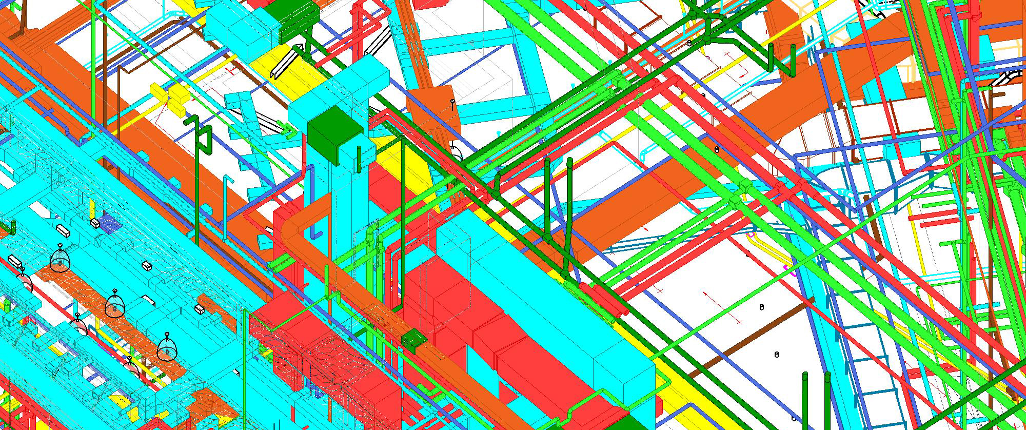
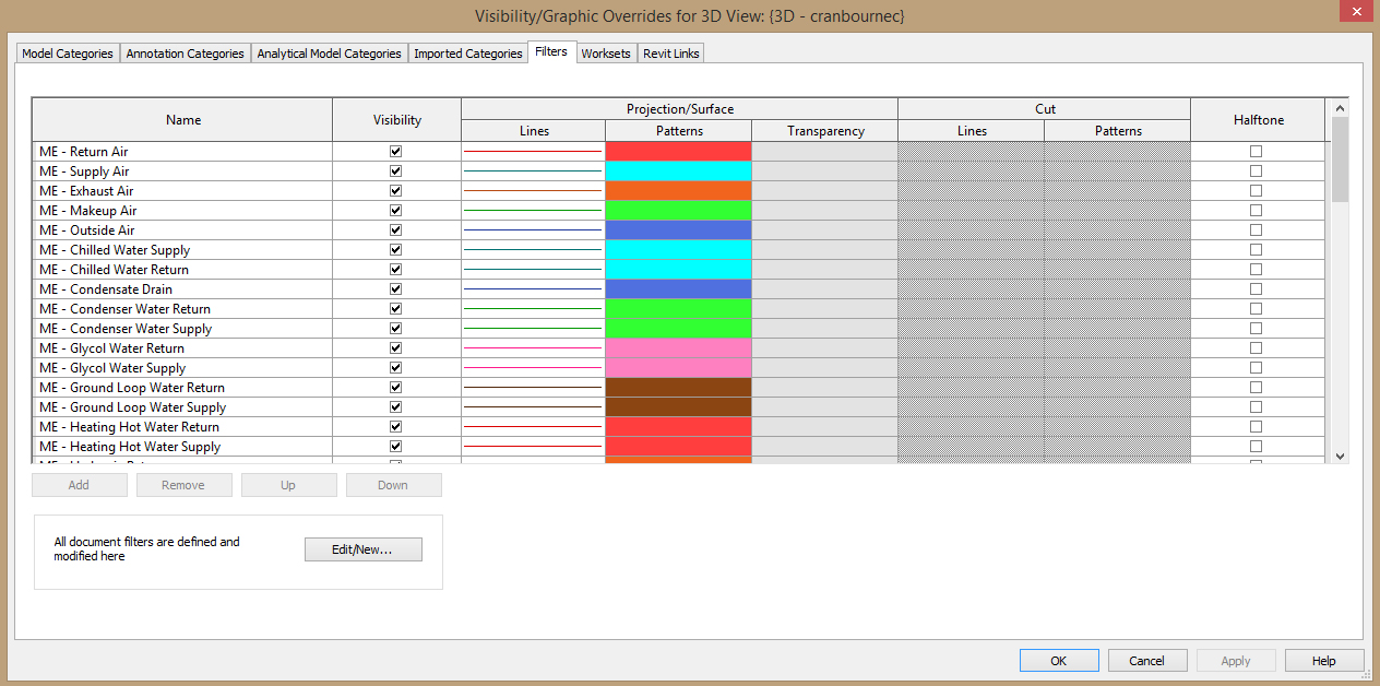
3. Add some color – Take some time to step out of your engineering shell and develop color filters for all Trades and Systems. This step takes you away from a sea of gray systems to readily identifiable components. Consider following ASHRAE standards for some common categorizations and effective R-G-B selections. Alternatively, make your own to suit company specific needs. Once you develop a company standard, stay true to it. Consistency is the key.
4. Routing Preferences – Ducts, pipes, and conduits can all default to using chosen fittings in specific circumstances. Go to “Edit Type” in the properties box and then edit routing preferences. Then only worry about exceptions to your set rules, rather than changing every fitting manually.

5. Draw sloped pipes upstream – Sloped pipes are the hardest component to model. Follow these instructions to make the process much easier:
- Start at the lowest point.
- Within the Place Pipe tab, specify “Slope Up” with the desired slope.
- Draw pipe in direction against flow.
- Add branches to your main by using the “Inherit Elevation” option in the Place Pipe tab.
Following these instructions keeps the direction of all connections consistent. Modeling downstream would cause the need to match all branch lines back into the same alignment and elevation as the main. This may mean pipes need to be adjusted up to be tight to steel. However, once modeled properly, the pipes will be much easier to adjust and reconnect.
It takes some time to get used to the seemingly odd ways system components in Revit behave. As long as you keep your models organized and try to keep consistent, systems modeling will become second nature.